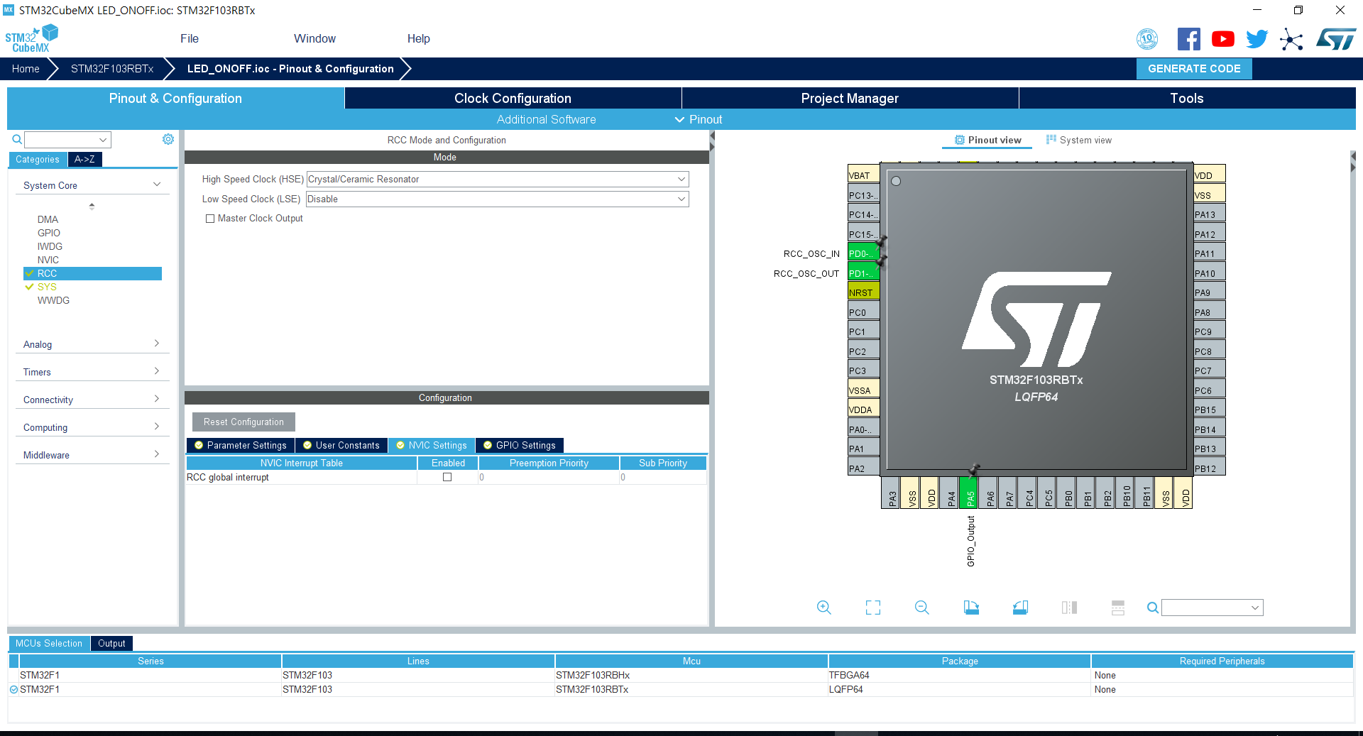
반응형


<CUBE MX 설정>

* Joystick : JOY_A, JOY_B, JOY_C, JOY_D, JOY_CTR, JOY_COM=GND, JOY_CTR

* LED : PD12, PD13, PD14, PD15

* Switch : KEY_USER, KEY_WAKEUP

* 동작원리 : Joystick이 Active low 일 때, LED On, JOY_CTR은 Enter 역할


/**
******************************************************************************
* File Name : main.c
* Description : Main program body
******************************************************************************
*
* COPYRIGHT(c) 2022 STMicroelectronics
*
* Redistribution and use in source and binary forms, with or without modification,
* are permitted provided that the following conditions are met:
* 1. Redistributions of source code must retain the above copyright notice,
* this list of conditions and the following disclaimer.
* 2. Redistributions in binary form must reproduce the above copyright notice,
* this list of conditions and the following disclaimer in the documentation
* and/or other materials provided with the distribution.
* 3. Neither the name of STMicroelectronics nor the names of its contributors
* may be used to endorse or promote products derived from this software
* without specific prior written permission.
*
* THIS SOFTWARE IS PROVIDED BY THE COPYRIGHT HOLDERS AND CONTRIBUTORS "AS IS"
* AND ANY EXPRESS OR IMPLIED WARRANTIES, INCLUDING, BUT NOT LIMITED TO, THE
* IMPLIED WARRANTIES OF MERCHANTABILITY AND FITNESS FOR A PARTICULAR PURPOSE ARE
* DISCLAIMED. IN NO EVENT SHALL THE COPYRIGHT HOLDER OR CONTRIBUTORS BE LIABLE
* FOR ANY DIRECT, INDIRECT, INCIDENTAL, SPECIAL, EXEMPLARY, OR CONSEQUENTIAL
* DAMAGES (INCLUDING, BUT NOT LIMITED TO, PROCUREMENT OF SUBSTITUTE GOODS OR
* SERVICES; LOSS OF USE, DATA, OR PROFITS; OR BUSINESS INTERRUPTION) HOWEVER
* CAUSED AND ON ANY THEORY OF LIABILITY, WHETHER IN CONTRACT, STRICT LIABILITY,
* OR TORT (INCLUDING NEGLIGENCE OR OTHERWISE) ARISING IN ANY WAY OUT OF THE USE
* OF THIS SOFTWARE, EVEN IF ADVISED OF THE POSSIBILITY OF SUCH DAMAGE.
*
******************************************************************************
*/
/* Includes ------------------------------------------------------------------*/
#include "main.h"
#include "stm32f4xx_hal.h"
#include "gpio.h"
/* USER CODE BEGIN Includes */
/* USER CODE END Includes */
/* Private variables ---------------------------------------------------------*/
/* USER CODE BEGIN PV */
/* Private variables ---------------------------------------------------------*/
/* USER CODE END PV */
/* Private function prototypes -----------------------------------------------*/
void SystemClock_Config(void);
void Error_Handler(void);
/* USER CODE BEGIN PFP */
/* Private function prototypes -----------------------------------------------*/
/* USER CODE END PFP */
/* USER CODE BEGIN 0 */
/* USER CODE END 0 */
int main(void)
{
/* USER CODE BEGIN 1 */
/* USER CODE END 1 */
/* MCU Configuration----------------------------------------------------------*/
/* Reset of all peripherals, Initializes the Flash interface and the Systick. */
HAL_Init();
/* Configure the system clock */
SystemClock_Config();
/* Initialize all configured peripherals */
MX_GPIO_Init();
/* USER CODE BEGIN 2 */
/* USER CODE END 2 */
/* Infinite loop */
/* USER CODE BEGIN WHILE */
while (1)
{
/* USER CODE END WHILE */
/* USER CODE BEGIN 3 */
/* A - LED1 */
if(HAL_GPIO_ReadPin(JOY_A_GPIO_Port, JOY_A_Pin) == GPIO_PIN_RESET)
HAL_GPIO_WritePin(LED1_GPIO_Port, LED1_Pin, GPIO_PIN_SET);
else
HAL_GPIO_WritePin(LED1_GPIO_Port, LED1_Pin, GPIO_PIN_RESET);

// ex) GPIO A포트의 JOY_A Pin이 Low면 LED ON

/* B - LED2 */
if(HAL_GPIO_ReadPin(JOY_B_GPIO_Port, JOY_B_Pin) == GPIO_PIN_RESET)
HAL_GPIO_WritePin(LED2_GPIO_Port, LED2_Pin, GPIO_PIN_SET);
else
HAL_GPIO_WritePin(LED2_GPIO_Port, LED2_Pin, GPIO_PIN_RESET);
/* C - LED3 */
if(HAL_GPIO_ReadPin(JOY_C_GPIO_Port, JOY_C_Pin) == GPIO_PIN_RESET)
HAL_GPIO_WritePin(LED3_GPIO_Port, LED3_Pin, GPIO_PIN_SET);
else
HAL_GPIO_WritePin(LED3_GPIO_Port, LED3_Pin, GPIO_PIN_RESET);
/* D - LED4 */
if(HAL_GPIO_ReadPin(JOY_D_GPIO_Port, JOY_D_Pin) == GPIO_PIN_RESET)
HAL_GPIO_WritePin(LED4_GPIO_Port, LED4_Pin, GPIO_PIN_SET);
else
HAL_GPIO_WritePin(LED4_GPIO_Port, LED4_Pin, GPIO_PIN_RESET);
/* PRESS - LED1 LED2 LED3 LED4 */
if(HAL_GPIO_ReadPin(JOY_CTR_GPIO_Port, JOY_CTR_Pin) == GPIO_PIN_RESET ||
HAL_GPIO_ReadPin(KEY_WAKEUP_GPIO_Port, KEY_WAKEUP_Pin) == GPIO_PIN_RESET ||
HAL_GPIO_ReadPin(KEY_USER_GPIO_Port, KEY_USER_Pin) == GPIO_PIN_RESET)

//JOY_CTR(enter)가 Low일때, KEY_WAKREUP, KEY_USER가 Low일 때,

{


HAL_GPIO_WritePin(LED1_GPIO_Port, LED1_Pin, GPIO_PIN_SET);
HAL_GPIO_WritePin(LED2_GPIO_Port, LED2_Pin, GPIO_PIN_SET);
HAL_GPIO_WritePin(LED3_GPIO_Port, LED3_Pin, GPIO_PIN_SET);
HAL_GPIO_WritePin(LED4_GPIO_Port, LED4_Pin, GPIO_PIN_SET);


}
else
{
HAL_GPIO_WritePin(LED1_GPIO_Port, LED1_Pin, GPIO_PIN_RESET);
HAL_GPIO_WritePin(LED2_GPIO_Port, LED2_Pin, GPIO_PIN_RESET);
HAL_GPIO_WritePin(LED3_GPIO_Port, LED3_Pin, GPIO_PIN_RESET);
HAL_GPIO_WritePin(LED4_GPIO_Port, LED4_Pin, GPIO_PIN_RESET);
}
}
/* USER CODE END 3 */
}
/** System Clock Configuration
*/
void SystemClock_Config(void)
{
RCC_OscInitTypeDef RCC_OscInitStruct;
RCC_ClkInitTypeDef RCC_ClkInitStruct;
/**Configure the main internal regulator output voltage


*/
__HAL_RCC_PWR_CLK_ENABLE();
__HAL_PWR_VOLTAGESCALING_CONFIG(PWR_REGULATOR_VOLTAGE_SCALE1);
/**Initializes the CPU, AHB and APB busses clocks
*/
RCC_OscInitStruct.OscillatorType = RCC_OSCILLATORTYPE_HSI;
RCC_OscInitStruct.HSIState = RCC_HSI_ON;
RCC_OscInitStruct.HSICalibrationValue = 16;
RCC_OscInitStruct.PLL.PLLState = RCC_PLL_ON;
RCC_OscInitStruct.PLL.PLLSource = RCC_PLLSOURCE_HSI;
RCC_OscInitStruct.PLL.PLLM = 8;
RCC_OscInitStruct.PLL.PLLN = 168;
RCC_OscInitStruct.PLL.PLLP = RCC_PLLP_DIV2;
RCC_OscInitStruct.PLL.PLLQ = 4;
if (HAL_RCC_OscConfig(&RCC_OscInitStruct) != HAL_OK)
{
Error_Handler();
}
/**Initializes the CPU, AHB and APB busses clocks
*/
RCC_ClkInitStruct.ClockType = RCC_CLOCKTYPE_HCLK|RCC_CLOCKTYPE_SYSCLK
|RCC_CLOCKTYPE_PCLK1|RCC_CLOCKTYPE_PCLK2;
RCC_ClkInitStruct.SYSCLKSource = RCC_SYSCLKSOURCE_PLLCLK;
RCC_ClkInitStruct.AHBCLKDivider = RCC_SYSCLK_DIV1;
RCC_ClkInitStruct.APB1CLKDivider = RCC_HCLK_DIV4;
RCC_ClkInitStruct.APB2CLKDivider = RCC_HCLK_DIV2;
if (HAL_RCC_ClockConfig(&RCC_ClkInitStruct, FLASH_LATENCY_5) != HAL_OK)
{
Error_Handler();
}
/**Configure the Systick interrupt time
*/
HAL_SYSTICK_Config(HAL_RCC_GetHCLKFreq()/1000);
/**Configure the Systick
*/
HAL_SYSTICK_CLKSourceConfig(SYSTICK_CLKSOURCE_HCLK);
/* SysTick_IRQn interrupt configuration */
HAL_NVIC_SetPriority(SysTick_IRQn, 0, 0);
}
/* USER CODE BEGIN 4 */
/* USER CODE END 4 */
/**
* @brief This function is executed in case of error occurrence.
* @param None
* @retval None
*/
void Error_Handler(void)
{
/* USER CODE BEGIN Error_Handler */
/* User can add his own implementation to report the HAL error return state */
while(1)
{
}
/* USER CODE END Error_Handler */
}
#ifdef USE_FULL_ASSERT
/**
* @brief Reports the name of the source file and the source line number
* where the assert_param error has occurred.
* @param file: pointer to the source file name
* @param line: assert_param error line source number
* @retval None
*/
void assert_failed(uint8_t* file, uint32_t line)
{
/* USER CODE BEGIN 6 */
/* User can add his own implementation to report the file name and line number,
ex: printf("Wrong parameters value: file %s on line %d\r\n", file, line) */
/* USER CODE END 6 */
}
#endif
/**
* @}
*/
/**
* @}
*/
/************************ (C) COPYRIGHT STMicroelectronics *****END OF FILE****/


Joystick, KEY Switch제어 시 LED가 켜지는 코드

반응형

'Project > Open407V-C' 카테고리의 다른 글

Open407V-C Timer 인터럽트(Timer 84hz Clock)  (0) 2022.06.13
OPEN407V-C TIMER 기본 동작  (0) 2022.04.01
OPEN407V-C EXIT 외부 인터럽트  (0) 2022.03.31
OPEN407V-C UART, Printf 제어  (0) 2022.03.30
Open407V-c package B  (0) 2022.01.06
반응형


/* USER CODE BEGIN Header */
/**
  ******************************************************************************
  * @file           : main.c
  * @brief          : Main program body
  ******************************************************************************
  * @attention
  *
  * <h2><center>&copy; Copyright (c) 2021 STMicroelectronics.
  * All rights reserved.</center></h2>
  *
  * This software component is licensed by ST under BSD 3-Clause license,
  * the "License"; You may not use this file except in compliance with the
  * License. You may obtain a copy of the License at:
  *                        opensource.org/licenses/BSD-3-Clause
  *
  ******************************************************************************
  */
/* USER CODE END Header */
/* Includes ------------------------------------------------------------------*/
#include "main.h"

//Char LCD Slave Address
#define SLAVE_ADDRESS_LCD 0x4E
////////////////////////////////////////////////////////////////////////////////

/* Private includes ----------------------------------------------------------*/
/* USER CODE BEGIN Includes */

/* USER CODE END Includes */

/* Private typedef -----------------------------------------------------------*/
/* USER CODE BEGIN PTD */

/* USER CODE END PTD */

/* Private define ------------------------------------------------------------*/
/* USER CODE BEGIN PD */
/* USER CODE END PD */

/* Private macro -------------------------------------------------------------*/
/* USER CODE BEGIN PM */

/* USER CODE END PM */

/* Private variables ---------------------------------------------------------*/
I2C_HandleTypeDef hi2c1;

UART_HandleTypeDef huart2;

/* USER CODE BEGIN PV */

//Char LCD func
void lcd_send_cmd (char cmd);
void lcd_send_data (char data);
void lcd_init (void);
void lcd_send_string (char *str);
void lcd_printxy(int x, int y, char *string);
void lcd_clear();
////////////////////////////////////////////////////////////////////////////////

/* USER CODE END PV */

/* Private function prototypes -----------------------------------------------*/
void SystemClock_Config(void);
static void MX_GPIO_Init(void);
static void MX_I2C1_Init(void);
static void MX_USART2_UART_Init(void);
/* USER CODE BEGIN PFP */

/* USER CODE END PFP */

/* Private user code ---------------------------------------------------------*/
/* USER CODE BEGIN 0 */

/* USER CODE END 0 */

/**
  * @brief  The application entry point.
  * @retval int
  */
int main(void)
{
  /* USER CODE BEGIN 1 */

  /* USER CODE END 1 */

  /* MCU Configuration--------------------------------------------------------*/

  /* Reset of all peripherals, Initializes the Flash interface and the Systick. */
  HAL_Init();

  /* USER CODE BEGIN Init */

  /* USER CODE END Init */

  /* Configure the system clock */
  SystemClock_Config();

  /* USER CODE BEGIN SysInit */

  /* USER CODE END SysInit */

  /* Initialize all configured peripherals */
  MX_GPIO_Init();
  MX_I2C1_Init();
  MX_USART2_UART_Init();
  /* USER CODE BEGIN 2 */

  // LCD Test
  lcd_init();
  lcd_clear();
  lcd_printxy(0, 0, "hello");
  lcd_printxy(0, 1, "hello2");
  HAL_Delay(1000);
  ////////////////////////////////////////////////////////////////////////////////

  /* USER CODE END 2 */

  /* Infinite loop */
  /* USER CODE BEGIN WHILE */
  while (1)
  {
    /* USER CODE END WHILE */

    /* USER CODE BEGIN 3 */
  }
  /* USER CODE END 3 */
}

// LCD Func detail
void lcd_send_cmd (char cmd)
{
  char data_u, data_l;
uint8_t data_t[4];
data_u = (cmd&0xf0);
data_l = ((cmd<<4)&0xf0);
data_t[0] = data_u|0x0C;  //en=1, rs=0
data_t[1] = data_u|0x08;  //en=0, rs=0
data_t[2] = data_l|0x0C;  //en=1, rs=0
data_t[3] = data_l|0x08;  //en=0, rs=0
HAL_I2C_Master_Transmit (&hi2c1, SLAVE_ADDRESS_LCD,(uint8_t *) data_t, 4, 100);
}
void lcd_send_data (char data)
{
char data_u, data_l;
uint8_t data_t[4];
data_u = (data&0xf0);
data_l = ((data<<4)&0xf0);
data_t[0] = data_u|0x0D;  //en=1, rs=1
data_t[1] = data_u|0x09;  //en=0, rs=1
data_t[2] = data_l|0x0D;  //en=1, rs=1
data_t[3] = data_l|0x09;  //en=0, rs=1
HAL_I2C_Master_Transmit (&hi2c1, SLAVE_ADDRESS_LCD,(uint8_t *) data_t, 4, 100);
}
void lcd_init (void)
{
// 4 bit initialisation
HAL_Delay(50);  // wait for >40ms
lcd_send_cmd (0x30);
HAL_Delay(5);  // wait for >4.1ms
lcd_send_cmd (0x30);
HAL_Delay(1);  // wait for >100us
lcd_send_cmd (0x30);
HAL_Delay(10);
lcd_send_cmd (0x20);  // 4bit mode
HAL_Delay(10);

  // dislay initialisation
lcd_send_cmd (0x28); // Function set --> DL=0 (4 bit mode), N = 1 (2 line display) F = 0 (5x8 characters)
HAL_Delay(1);
lcd_send_cmd (0x08); //Display on/off control --> D=0,C=0, B=0  ---> display off
HAL_Delay(1);
lcd_send_cmd (0x01);  // clear display
HAL_Delay(1);
HAL_Delay(1);
lcd_send_cmd (0x06); //Entry mode set --> I/D = 1 (increment cursor) & S = 0 (no shift)
HAL_Delay(1);
lcd_send_cmd (0x0C); //Display on/off control --> D = 1, C and B = 0. (Cursor and blink, last two bits)
}
void lcd_send_string (char *str)
{
while (*str) lcd_send_data (*str++);
}
void lcd_gotoxy(int x, int y)
{
lcd_send_cmd(0x80 | (0x40 * y) | x);
}
void lcd_printxy(int x, int y, char *string)  { // display a string on LCD
   lcd_gotoxy(x, y);
   while(*string != '\0') { // display string
   lcd_send_data(*string);
      string++;
   }
}
void lcd_clear()
{
lcd_send_cmd(0x01); // clear display
    HAL_Delay(10);

}
////////////////////////////////////////////////////////////////////////////////

/**
  * @brief System Clock Configuration
  * @retval None
  */
void SystemClock_Config(void)
{
  RCC_OscInitTypeDef RCC_OscInitStruct = {0};
  RCC_ClkInitTypeDef RCC_ClkInitStruct = {0};

  /** Initializes the RCC Oscillators according to the specified parameters
  * in the RCC_OscInitTypeDef structure.
  */
  RCC_OscInitStruct.OscillatorType = RCC_OSCILLATORTYPE_HSI;
  RCC_OscInitStruct.HSIState = RCC_HSI_ON;
  RCC_OscInitStruct.HSICalibrationValue = RCC_HSICALIBRATION_DEFAULT;
  RCC_OscInitStruct.PLL.PLLState = RCC_PLL_ON;
  RCC_OscInitStruct.PLL.PLLSource = RCC_PLLSOURCE_HSI_DIV2;
  RCC_OscInitStruct.PLL.PLLMUL = RCC_PLL_MUL16;
  if (HAL_RCC_OscConfig(&RCC_OscInitStruct) != HAL_OK)
  {
    Error_Handler();
  }
  /** Initializes the CPU, AHB and APB buses clocks
  */
  RCC_ClkInitStruct.ClockType = RCC_CLOCKTYPE_HCLK|RCC_CLOCKTYPE_SYSCLK
                              |RCC_CLOCKTYPE_PCLK1|RCC_CLOCKTYPE_PCLK2;
  RCC_ClkInitStruct.SYSCLKSource = RCC_SYSCLKSOURCE_PLLCLK;
  RCC_ClkInitStruct.AHBCLKDivider = RCC_SYSCLK_DIV1;
  RCC_ClkInitStruct.APB1CLKDivider = RCC_HCLK_DIV2;
  RCC_ClkInitStruct.APB2CLKDivider = RCC_HCLK_DIV1;

  if (HAL_RCC_ClockConfig(&RCC_ClkInitStruct, FLASH_LATENCY_2) != HAL_OK)
  {
    Error_Handler();
  }
}

/**
  * @brief I2C1 Initialization Function
  * @param None
  * @retval None
  */
static void MX_I2C1_Init(void)
{

  /* USER CODE BEGIN I2C1_Init 0 */

  /* USER CODE END I2C1_Init 0 */

  /* USER CODE BEGIN I2C1_Init 1 */

  /* USER CODE END I2C1_Init 1 */
  hi2c1.Instance = I2C1;
  hi2c1.Init.ClockSpeed = 100000;
  hi2c1.Init.DutyCycle = I2C_DUTYCYCLE_2;
  hi2c1.Init.OwnAddress1 = 0;
  hi2c1.Init.AddressingMode = I2C_ADDRESSINGMODE_7BIT;
  hi2c1.Init.DualAddressMode = I2C_DUALADDRESS_DISABLE;
  hi2c1.Init.OwnAddress2 = 0;
  hi2c1.Init.GeneralCallMode = I2C_GENERALCALL_DISABLE;
  hi2c1.Init.NoStretchMode = I2C_NOSTRETCH_DISABLE;
  if (HAL_I2C_Init(&hi2c1) != HAL_OK)
  {
    Error_Handler();
  }
  /* USER CODE BEGIN I2C1_Init 2 */

  /* USER CODE END I2C1_Init 2 */

}

/**
  * @brief USART2 Initialization Function
  * @param None
  * @retval None
  */
static void MX_USART2_UART_Init(void)
{

  /* USER CODE BEGIN USART2_Init 0 */

  /* USER CODE END USART2_Init 0 */

  /* USER CODE BEGIN USART2_Init 1 */

  /* USER CODE END USART2_Init 1 */
  huart2.Instance = USART2;
  huart2.Init.BaudRate = 115200;
  huart2.Init.WordLength = UART_WORDLENGTH_8B;
  huart2.Init.StopBits = UART_STOPBITS_1;
  huart2.Init.Parity = UART_PARITY_NONE;
  huart2.Init.Mode = UART_MODE_TX_RX;
  huart2.Init.HwFlowCtl = UART_HWCONTROL_NONE;
  huart2.Init.OverSampling = UART_OVERSAMPLING_16;
  if (HAL_UART_Init(&huart2) != HAL_OK)
  {
    Error_Handler();
  }
  /* USER CODE BEGIN USART2_Init 2 */

  /* USER CODE END USART2_Init 2 */

}

/**
  * @brief GPIO Initialization Function
  * @param None
  * @retval None
  */
static void MX_GPIO_Init(void)
{
  GPIO_InitTypeDef GPIO_InitStruct = {0};

  /* GPIO Ports Clock Enable */
  __HAL_RCC_GPIOC_CLK_ENABLE();
  __HAL_RCC_GPIOD_CLK_ENABLE();
  __HAL_RCC_GPIOA_CLK_ENABLE();
  __HAL_RCC_GPIOB_CLK_ENABLE();

  /*Configure GPIO pin Output Level */
  HAL_GPIO_WritePin(LD2_GPIO_Port, LD2_Pin, GPIO_PIN_RESET);

  /*Configure GPIO pin : B1_Pin */
  GPIO_InitStruct.Pin = B1_Pin;
  GPIO_InitStruct.Mode = GPIO_MODE_IT_RISING;
  GPIO_InitStruct.Pull = GPIO_NOPULL;
  HAL_GPIO_Init(B1_GPIO_Port, &GPIO_InitStruct);

  /*Configure GPIO pin : LD2_Pin */
  GPIO_InitStruct.Pin = LD2_Pin;
  GPIO_InitStruct.Mode = GPIO_MODE_OUTPUT_PP;
  GPIO_InitStruct.Pull = GPIO_NOPULL;
  GPIO_InitStruct.Speed = GPIO_SPEED_FREQ_LOW;
  HAL_GPIO_Init(LD2_GPIO_Port, &GPIO_InitStruct);

  /* EXTI interrupt init*/
  HAL_NVIC_SetPriority(EXTI15_10_IRQn, 0, 0);
  HAL_NVIC_EnableIRQ(EXTI15_10_IRQn);

}

/* USER CODE BEGIN 4 */

/* USER CODE END 4 */

/**
  * @brief  This function is executed in case of error occurrence.
  * @retval None
  */
void Error_Handler(void)
{
  /* USER CODE BEGIN Error_Handler_Debug */
  /* User can add his own implementation to report the HAL error return state */
  __disable_irq();
  while (1)
  {
  }
  /* USER CODE END Error_Handler_Debug */
}

#ifdef  USE_FULL_ASSERT
/**
  * @brief  Reports the name of the source file and the source line number
  *         where the assert_param error has occurred.
  * @param  file: pointer to the source file name
  * @param  line: assert_param error line source number
  * @retval None
  */
void assert_failed(uint8_t *file, uint32_t line)
{
  /* USER CODE BEGIN 6 */
  /* User can add his own implementation to report the file name and line number,
     ex: printf("Wrong parameters value: file %s on line %d\r\n", file, line) */
  /* USER CODE END 6 */
}
#endif /* USE_FULL_ASSERT */

/************************ (C) COPYRIGHT STMicroelectronics *****END OF FILE****/


참고 Link : https://controllerstech.com/i2c-lcd-in-stm32/

반응형

'Project > Nucleo-F103RB' 카테고리의 다른 글

Nucleo-F103RB Serial통신 RingBuff  (0) 2023.04.13
Nucleo-F103RB Serial 통신3  (0) 2019.05.27
Nucleo-F103RB Serial 통신2  (0) 2019.05.21
Nucleo-F103RB 시리얼통신 입력으로 제어  (0) 2019.05.21
Nucleo-F103RB Serial 통신1  (0) 2019.05.21
반응형

1. CUBE MX 설정


/* USER CODE BEGIN Header */
/**
  ******************************************************************************
  * @file           : main.c
  * @brief          : Main program body
  ******************************************************************************
  * @attention
  *
  * 

© Copyright (c) 2019 STMicroelectronics.
  * All rights reserved.


  *
  * This software component is licensed by ST under BSD 3-Clause license,
  * the "License"; You may not use this file except in compliance with the
  * License. You may obtain a copy of the License at:
  *                        opensource.org/licenses/BSD-3-Clause
  *
  ******************************************************************************
  */
/* USER CODE END Header */

/* Includes ------------------------------------------------------------------*/
#include "main.h"

/* Private includes ----------------------------------------------------------*/
/* USER CODE BEGIN Includes */

/* USER CODE END Includes */

/* Private typedef -----------------------------------------------------------*/
/* USER CODE BEGIN PTD */

/* USER CODE END PTD */

/* Private define ------------------------------------------------------------*/
/* USER CODE BEGIN PD */

/* USER CODE END PD */

/* Private macro -------------------------------------------------------------*/
/* USER CODE BEGIN PM */

/* USER CODE END PM */

/* Private variables ---------------------------------------------------------*/
UART_HandleTypeDef huart2;

/* USER CODE BEGIN PV */

/* USER CODE END PV */

/* Private function prototypes -----------------------------------------------*/
void SystemClock_Config(void);
static void MX_GPIO_Init(void);
static void MX_USART2_UART_Init(void);
/* USER CODE BEGIN PFP */

/* USER CODE END PFP */

/* Private user code ---------------------------------------------------------*/
/* USER CODE BEGIN 0 */

/* USER CODE END 0 */

/**
  * @brief  The application entry point.
  * @retval int
  */
int fputc(int ch, FILE *f) 

uint8_t temp[1] = {ch} ; 

HAL_UART_Transmit(&huart2, temp, 1, 50) ; 

return(ch) ; 

/*

내부 정의된 함수들로 Printf를 사용할 수 있게 해준다.

*/
int main(void)
{
  /* USER CODE BEGIN 1 */

  /* USER CODE END 1 */
  

  /* MCU Configuration--------------------------------------------------------*/

  /* Reset of all peripherals, Initializes the Flash interface and the Systick. */
  HAL_Init();

  /* USER CODE BEGIN Init */

  /* USER CODE END Init */

  /* Configure the system clock */
  SystemClock_Config();

  /* USER CODE BEGIN SysInit */

  /* USER CODE END SysInit */

  /* Initialize all configured peripherals */
  MX_GPIO_Init();
  MX_USART2_UART_Init();
  /* USER CODE BEGIN 2 */

HAL_StatusTypeDef RcvStat ;  //rcvStat 상태 변수 선언
uint8_t bufftx[10] = "Hello!\n" ;  //bufftx배열에 문자열 삽입
uint8_t UsartData[10] ;  //UsartData 배열 선언

//HAL_UART_Transmit(&huart2, bufftx, 10, 100);  // send start data 

  /* USER CODE END 2 */

  /* Infinite loop */
  /* USER CODE BEGIN WHILE */
  while (1)
  {
    /* USER CODE END WHILE */

    /* USER CODE BEGIN 3 */

/*
// 1. continue TX Data
HAL_UART_Transmit(&huart2, bufftx, 10, 100) ;  // send start data 
*/ //송신 

/*
// 2. loopback TX Data
RcvStat = HAL_UART_Receive(&huart2, UsartData, 1, 100) ;  // receive data 

if (RcvStat == HAL_OK) {  // receive check 
HAL_UART_Transmit(&huart2, UsartData, 1, 100) ;  // send received data 
}  //Receive loopback code
*/

/*
// 3. printf TX Data, need function call
printf("Hello\n") ; 
HAL_Delay(500) ; 
*/  // printf 함수 사용 0.5초마다 송신

  }
  /* USER CODE END 3 */
}

/**
  * @brief System Clock Configuration
  * @retval None
  */
void SystemClock_Config(void)
{
  RCC_OscInitTypeDef RCC_OscInitStruct = {0};
  RCC_ClkInitTypeDef RCC_ClkInitStruct = {0};

  /** Initializes the CPU, AHB and APB busses clocks 
  */
  RCC_OscInitStruct.OscillatorType = RCC_OSCILLATORTYPE_HSI;
  RCC_OscInitStruct.HSIState = RCC_HSI_ON;
  RCC_OscInitStruct.HSICalibrationValue = RCC_HSICALIBRATION_DEFAULT;
  RCC_OscInitStruct.PLL.PLLState = RCC_PLL_NONE;
  if (HAL_RCC_OscConfig(&RCC_OscInitStruct) != HAL_OK)
  {
    Error_Handler();
  }
  /** Initializes the CPU, AHB and APB busses clocks 
  */
  RCC_ClkInitStruct.ClockType = RCC_CLOCKTYPE_HCLK|RCC_CLOCKTYPE_SYSCLK
                              |RCC_CLOCKTYPE_PCLK1|RCC_CLOCKTYPE_PCLK2;
  RCC_ClkInitStruct.SYSCLKSource = RCC_SYSCLKSOURCE_HSI;
  RCC_ClkInitStruct.AHBCLKDivider = RCC_SYSCLK_DIV1;
  RCC_ClkInitStruct.APB1CLKDivider = RCC_HCLK_DIV1;
  RCC_ClkInitStruct.APB2CLKDivider = RCC_HCLK_DIV1;

  if (HAL_RCC_ClockConfig(&RCC_ClkInitStruct, FLASH_LATENCY_0) != HAL_OK)
  {
    Error_Handler();
  }
}

/**
  * @brief USART2 Initialization Function
  * @param None
  * @retval None
  */
static void MX_USART2_UART_Init(void)
{

  /* USER CODE BEGIN USART2_Init 0 */

  /* USER CODE END USART2_Init 0 */

  /* USER CODE BEGIN USART2_Init 1 */

  /* USER CODE END USART2_Init 1 */
  huart2.Instance = USART2;
  huart2.Init.BaudRate = 115200;
  huart2.Init.WordLength = UART_WORDLENGTH_8B;
  huart2.Init.StopBits = UART_STOPBITS_1;
  huart2.Init.Parity = UART_PARITY_NONE;
  huart2.Init.Mode = UART_MODE_TX_RX;
  huart2.Init.HwFlowCtl = UART_HWCONTROL_NONE;
  huart2.Init.OverSampling = UART_OVERSAMPLING_16;
  if (HAL_UART_Init(&huart2) != HAL_OK)
  {
    Error_Handler();
  }
  /* USER CODE BEGIN USART2_Init 2 */

  /* USER CODE END USART2_Init 2 */

}

/**
  * @brief GPIO Initialization Function
  * @param None
  * @retval None
  */
static void MX_GPIO_Init(void)
{
  GPIO_InitTypeDef GPIO_InitStruct = {0};

  /* GPIO Ports Clock Enable */
  __HAL_RCC_GPIOC_CLK_ENABLE();
  __HAL_RCC_GPIOA_CLK_ENABLE();

  /*Configure GPIO pin Output Level */
  HAL_GPIO_WritePin(GPIOA, GPIO_PIN_6, GPIO_PIN_RESET);

  /*Configure GPIO pin : PC13 */
  GPIO_InitStruct.Pin = GPIO_PIN_13;
  GPIO_InitStruct.Mode = GPIO_MODE_INPUT;
  GPIO_InitStruct.Pull = GPIO_NOPULL;
  HAL_GPIO_Init(GPIOC, &GPIO_InitStruct);

  /*Configure GPIO pin : PA6 */
  GPIO_InitStruct.Pin = GPIO_PIN_6;
  GPIO_InitStruct.Mode = GPIO_MODE_OUTPUT_PP;
  GPIO_InitStruct.Pull = GPIO_NOPULL;
  GPIO_InitStruct.Speed = GPIO_SPEED_FREQ_LOW;
  HAL_GPIO_Init(GPIOA, &GPIO_InitStruct);

}

/* USER CODE BEGIN 4 */

/* USER CODE END 4 */

/**
  * @brief  This function is executed in case of error occurrence.
  * @retval None
  */
void Error_Handler(void)
{
  /* USER CODE BEGIN Error_Handler_Debug */
  /* User can add his own implementation to report the HAL error return state */

  /* USER CODE END Error_Handler_Debug */
}

#ifdef  USE_FULL_ASSERT
/**
  * @brief  Reports the name of the source file and the source line number
  *         where the assert_param error has occurred.
  * @param  file: pointer to the source file name
  * @param  line: assert_param error line source number
  * @retval None
  */
void assert_failed(uint8_t *file, uint32_t line)

  /* USER CODE BEGIN 6 */
  /* User can add his own implementation to report the file name and line number,
     tex: printf("Wrong parameters value: file %s on line %d\r\n", file, line) */
  /* USER CODE END 6 */
}
#endif /* USE_FULL_ASSERT */

/************************ (C) COPYRIGHT STMicroelectronics *****END OF FILE****/


다음은 링버퍼를 구현해보도록 하겠습니다.

반응형

'Project > Nucleo-F103RB' 카테고리의 다른 글

Nucleo-F103RB Serial통신 RingBuff  (0) 2023.04.13
Nucleo 103rb i2c Char LCD  (0) 2021.05.25
Nucleo-F103RB Serial 통신2  (0) 2019.05.21
Nucleo-F103RB 시리얼통신 입력으로 제어  (0) 2019.05.21
Nucleo-F103RB Serial 통신1  (0) 2019.05.21
반응형

스위치를 이용한 입력으로 시리얼 전송

시리얼 문자를 이용한 LED OnOFF


1. CUBE MX SET


2. Sorce Code

int main(void)
{
  /* USER CODE BEGIN 1 */

  /* USER CODE END 1 */
  

  /* MCU Configuration--------------------------------------------------------*/

  /* Reset of all peripherals, Initializes the Flash interface and the Systick. */
  HAL_Init();

  /* USER CODE BEGIN Init */

  /* USER CODE END Init */

  /* Configure the system clock */
  SystemClock_Config();

  /* USER CODE BEGIN SysInit */

  /* USER CODE END SysInit */

  /* Initialize all configured peripherals */
  MX_GPIO_Init();
  MX_USART2_UART_Init();
  /* USER CODE BEGIN 2 */
HAL_StatusTypeDef RcvStat ;
uint8_t bufftx[10] = "Hello!\n" ;
uint8_t b_in[10] = "b_in\n" ;
uint8_t UsartData[10] ;
uint8_t pin_state ;

HAL_UART_Transmit(&huart2, bufftx, 10, 100) ;
  /* USER CODE END 2 */

  /* Infinite loop */
  /* USER CODE BEGIN WHILE */
  while (1)
  {
    /* USER CODE END WHILE */

    /* USER CODE BEGIN 3 */
RcvStat = HAL_UART_Receive(&huart2, UsartData, 1, 100) ;

if (RcvStat == HAL_OK) {
if (UsartData[0] == 'a') {  // if serial input is 'a', led on
HAL_GPIO_WritePin(GPIOA, GPIO_PIN_5, GPIO_PIN_SET) ;
} else if (UsartData[0] == 'b') {  // if serial input is 'a', led off
HAL_GPIO_WritePin(GPIOA, GPIO_PIN_5, GPIO_PIN_RESET) ;
}

HAL_UART_Transmit(&huart2, UsartData, 1, 100) ;
}

pin_state = HAL_GPIO_ReadPin(GPIOC, GPIO_PIN_13) ;

if (!pin_state) {  // if b1 is low, send b_in
HAL_UART_Transmit(&huart2, b_in, 10, 100) ;
}
  }
  /* USER CODE END 3 */
}


SWITCH를 누르면 B_IN MSG 송신

시리얼문자 'a' 전송시 LED ON

'b'전송시 LED OFF

반응형

'Project > Nucleo-F103RB' 카테고리의 다른 글

Nucleo-F103RB Serial 통신3  (0) 2019.05.27
Nucleo-F103RB Serial 통신2  (0) 2019.05.21
Nucleo-F103RB Serial 통신1  (0) 2019.05.21
Nucleo-F103RB LED 켜기  (0) 2019.05.21
Nucleo-F103RB 개발환경  (0) 2019.05.21
반응형

1. CUBE MX SET


2. GENERATE CODE


3. Sorce Code


int main(void)
{
  /* USER CODE BEGIN 1 */

  /* USER CODE END 1 */
  

  /* MCU Configuration--------------------------------------------------------*/

  /* Reset of all peripherals, Initializes the Flash interface and the Systick. */
  HAL_Init();

  /* USER CODE BEGIN Init */

  /* USER CODE END Init */

  /* Configure the system clock */
  SystemClock_Config();

  /* USER CODE BEGIN SysInit */

  /* USER CODE END SysInit */

  /* Initialize all configured peripherals */
  MX_GPIO_Init();
  MX_USART2_UART_Init();
  /* USER CODE BEGIN 2 */
HAL_StatusTypeDef RcvStat ;
uint8_t bufftx[10] = "Hello!\n" ;
uint8_t UsartData[10] ;

HAL_UART_Transmit(&huart2, bufftx, 10, 100) ;  // send start data
  /* USER CODE END 2 */

  /* Infinite loop */
  /* USER CODE BEGIN WHILE */
  while (1)
  {
    /* USER CODE END WHILE */

    /* USER CODE BEGIN 3 */
RcvStat = HAL_UART_Receive(&huart2, UsartData, 1, 100) ;  // receive data

if (RcvStat == HAL_OK) {  // receive check
HAL_UART_Transmit(&huart2, UsartData, 1, 100) ;  // send received data
}
  }
  /* USER CODE END 3 */
}


코드는 좀더 들여다 봐야 할 것 같다....


Interrupt Enable은 왜 했는지?

Serial 확인시 1번만 수신되고, Loopback 기능인 것 같다.


반응형

'Project > Nucleo-F103RB' 카테고리의 다른 글

Nucleo-F103RB Serial 통신3  (0) 2019.05.27
Nucleo-F103RB Serial 통신2  (0) 2019.05.21
Nucleo-F103RB 시리얼통신 입력으로 제어  (0) 2019.05.21
Nucleo-F103RB LED 켜기  (0) 2019.05.21
Nucleo-F103RB 개발환경  (0) 2019.05.21
반응형

개발환경 CUBE MX + Keil


1. 프로젝트 생성 및 RCC 설정

- HSE 외부 크리스탈 사용(이미지 참고)


2. PA5 Output 설정


3. Code GENERATE 실행


4. Source Code 


int main(void)
{
  /* USER CODE BEGIN 1 */

  /* USER CODE END 1 */
  

  /* MCU Configuration--------------------------------------------------------*/

  /* Reset of all peripherals, Initializes the Flash interface and the Systick. */
  HAL_Init();

  /* USER CODE BEGIN Init */

  /* USER CODE END Init */

  /* Configure the system clock */
  SystemClock_Config();

  /* USER CODE BEGIN SysInit */

  /* USER CODE END SysInit */

  /* Initialize all configured peripherals */
  MX_GPIO_Init();
  /* USER CODE BEGIN 2 */

  /* USER CODE END 2 */

  /* Infinite loop */
  /* USER CODE BEGIN WHILE */
  while (1)
  {
    /* USER CODE END WHILE */

    /* USER CODE BEGIN 3 */
/*
HAL_GPIO_WritePin(GPIOA, GPIO_PIN_5, GPIO_PIN_SET);
HAL_Delay(1000);

HAL_GPIO_WritePin(GPIOA, GPIO_PIN_5, GPIO_PIN_RESET);
HAL_Delay(1000);

*/

// 두 코드 모두 동일 한 기능 수행


HAL_GPIO_TogglePin(GPIOA,GPIO_PIN_5);
HAL_Delay(1000);

HAL_GPIO_TogglePin(GPIOA,GPIO_PIN_5);
HAL_Delay(1000);
  }
  /* USER CODE END 3 */
}


5. F7 빌드 F8 컴파일


6. 컴파일 후 적용되지 않아 봤더니 Reset을 한번 해 주어야 함...

- 왜그런지는 잘 모르겠음... 일단 빌드업 부터 동작 확인 완료


다음 과제는 UART Serial 통신 구현

반응형

'Project > Nucleo-F103RB' 카테고리의 다른 글

Nucleo-F103RB Serial 통신3  (0) 2019.05.27
Nucleo-F103RB Serial 통신2  (0) 2019.05.21
Nucleo-F103RB 시리얼통신 입력으로 제어  (0) 2019.05.21
Nucleo-F103RB Serial 통신1  (0) 2019.05.21
Nucleo-F103RB 개발환경  (0) 2019.05.21
반응형

CUBE MX + Keil 

HAL 드라이버를 이용한 개발환경 구성

SYS, RCC 클럭 설정 내부클럭, 외부클럭 설정 방법 및 적용 방법


1. CUBE MX 새 프로젝트 생성

제품군 선택


2. Start Project


3. MCU UI와 새로운 프로젝트 생성이 됨.


4. 기본적으로 LED를 켜기위해 PA5 Output 설정만으로 LED를 켜고 끌 수 있음.


5. 클럭 설정은 PD0, PD1을 RCC_OSC_IN, RCC_OSC_OUT으로 설정한 뒤, 카테고리의 System Core탭 에서 설정이 가능하다.

설정이 되지 않을 경우 해당 핀이 주황색으로 출력이 되는 것을 볼 수 있다.


HSE 값을 crystal/ceramic resonator로 설정을 하게 되면 다음과 같이 핀이 녹색으로 정상적으로 적용이 된 것을 볼 수 있다.


6. Project Manger탭에 진입하여, 프로젝트 네임과 저장할 경로를 설정한다.


7. 나는 Keil V5를 사용할 것이기 때문에 Toolchain/IDE의 선택을 MDK-ARM V5로 선택한다.

자, 이제 설정이 완료되면 우측 상단의 GENERATE CODE버튼을 클릭하면 로딩바가 출력되며 완료시 폴더를 열지 Project를 열지 팝업 창이 출력된다.


다음 포스팅에서 LED를 OnOFF 참고.


반응형

'Project > Nucleo-F103RB' 카테고리의 다른 글

Nucleo-F103RB Serial 통신3  (0) 2019.05.27
Nucleo-F103RB Serial 통신2  (0) 2019.05.21
Nucleo-F103RB 시리얼통신 입력으로 제어  (0) 2019.05.21
Nucleo-F103RB Serial 통신1  (0) 2019.05.21
Nucleo-F103RB LED 켜기  (0) 2019.05.21

+ Recent posts